Summary
Battery Energy Storage Systems have seen increasing volumes of deployment largely due to decreasing system costs, extended warranties and new markets for BESS services, even for longer duration systems above four hours. This expansion has brought key risks to the BESS operators, investors and lenders to evaluate and forecast performance (particularly in relation to battery degradation estimates) due to ambiguity in terminologies, specification and operation of batteries. Battery performance risks are typically managed through warranties, however warranties can be difficult to specify due to variation in battery technology and use cases. To mitigate these challenges, warranties should include definition of all key project parameters, properly referenced standards and independent testing requirements.
Introduction
The increasing demand of Battery Energy Storage System (BESS) has enabled grid operators to take advantage of these systems due the faster-response frame when compared to other renewable technologies. Smarter and automotive grids have allowed BESS (particularly Li-ion type) to access new markets. As different markets/services for BESS are integrated onto the system, the batteries have to perform in different (dis)charging rates having an uncertainty factor in battery degradation and consequently the lifespan of the system.
Most battery Original Equipment Manufacturers (OEM) provide warranties that cover product defects and guarantee performance. Guarantee performance warranties are currently not well standardised, and in times not well defined, across OEMs, the lack of fundamental guarantee performance definitions in the industry leads to not having one warranty that appropriately manages performance risk across the lifetime of the system.
Battery Energy Storage Performance Warranties
There are three main objectives behind most standard battery performance warranties (for BESS Li-ion type). Firstly, it attempts to frame the life cycle economics of the battery from beginning to end of life (BOL/EOL) based on one particular mode of use. Secondly, warranties tend to guarantee performance based on performance metrics defined, and most of the time, by only the available energy capacity (kWh) at a particular year, depending on a number of cycles which do not necessarily have a true reflection in battery degradation.
Additionally, these warranties tend to exclude any other main component such as the power conversion system/inverter. Thirdly, the battery industry is also lacking a robust and independent testing program shadowed by the ambiguity within national and international standards; strengthening these limitations is fundamental to the future of the industry.
Economics
Whilst system cost declines have been the most critical trend in energy storage economics in the past years, BloombergNEF estimates showed that improving systems durability is the critical driver in the cost of storing energy in 2020. The capex of building grid-scale battery storage plants has dropped 38 % in two years, from $471 to $293 per KWh for four-hour systems, before prices spike due to difficulties sourcing row material and volatility in the mineral market late in 2021. One possible way to further reduce costing on BESS and increasing confidence in the market is by securing longer battery durability throughout clearly defined and standardised warranties across OEMs
Although, this is an important indicator, longer warranties still do not create technical transparency to how the guaranteed performances are projected. Warranties based only on number of cycles do not reflect the true correlation with battery BOL capacity, aging and energy holding close to EOL. Therefore, a potential solution is to implement energy throughput securities (MW/MWh or often referred as MWh) as the main performance metric across all OEMs.
Performance Metrics
As briefly introduced in above, Energy Throughput (or sometimes referred in warranties as the minimum capacity retained by the battery at a particular year) is a comprehensive metric that evaluates the total energy an a OEM expects the battery to deliver throughout its lifetime. The critical limitation could arise that new services/usage for BESS are appearing changing the original intent of use and therefore compromising warranted capacity. Nevertheless, due to the lack of standardisation, the end user is still digesting major performance risks in evaluating these warranties.
The summary below shows the summarises relevant parameters (covered and not) in warranty performance that need better clarity from OEMs to understand (and possibly validate) the impact in the degradation of the batteries.
Covered by Warranties - Suggested Improvement
Energy Capacity and Degradation
- Clarification of sensitivity of energy throughput against degradation (SOC over C-rate, vice versa or optimal combination)
- Technology is evolving fast; clarification is needed to how test parameters and environments are relevant to the predicted degradation when implemented
- Clear definition of gain of energy throughput against internal battery losses induced
State of Charge SOC
- Definition of batteries operation to find optimum SOC rate, depending on the type of use (weather at low, medium, or high SOC windows)
- Benefits/impact when integration to the rest of the system in a BESS
- Clarification on impact of calendar aging vs used is predicted
- Clarification in how high DC voltage, while battery storing energy for long period of time, impact SOC
Cell Temperature
- Benefits of different types cells cooling (air-cooling and liquid-cooling systems)
- Understanding of temperature conditions in degrading battery cells versus different uses
- STC temperatures (Tamb=~25 °C) do not represent temperatures where most of operational BESS are located
- Tolerance against colder or hotter climates
- Impact on different SOC against RTE and degradation
- Mitigations against harsh environment conditions (i.e. humidity, dust, ambient temperature)
- Impact of climate change in ambient temperature when designing the sizing of the HVAC how humidity is detected in the battery cells within battery modules
Power Capacity
- Some OEMs do not guarantee power capacity (i.e. excluding the PCS components)
- Clarifications in how to optimally operate batteries at particular power rates
- Clarifications of how different rated powers impact C-rates (or current density- flux, on the cell) accelerating degradation
C-rate
- C-rate is a misleading term. Allows to false performance interpretation which can highly benefit the OEMs
- Clarification in how C-rates (currently defined) are impacted by points beforementioned points
Not Covered by Warranties - Suggested Improvement
Round-Trip Efficiency (RTE)
- Definitions of how burst discharge and fast charging impact the C-rate and therefore the RTE in the BESS as whole
- OEMs take advantage in passing this risk to the end user (and end user to the EPC)
- OEMs should be taken into account
- Better understanding of how BESS idle mode, in the whole system, affects the RTE and therefore apports to degradation
Auxiliary Load
- Particularly important for HVAC (air-cooling) system (impacting all points mentioned above), if the LV supply comes from the LV winding of the transformer after the PCS
- Major risk passed to the end user
- Not clear parameter to prevent voiding the battery warranty if HVAC performance is not adequate
Network Connectivity Access
- A limited number of OEMs are providing comprehensive warranties, flexible to analyse usage to adapt a system's energy capacity warranty to fit the end use profile
- Limited to location with access to network
- National and international regulation required to protect end user
- Lack of clarity how OEMs recalculate energy capacity warranties and how this represents a fair approach
- Original predicted performance by end user can dramatically change by voiding the warranty due connectivity issues
Improvement on Independent Testing Review and Standardisation
When comparing to different type of projects in the renewable energy industry such as solar or wind technologies, one can realise that standards for battery performance are less specific. This can be argued due to the immaturity of the technology, or chemistry used, and the fast changes it must adapt in a short timeframe. However, it can be disputable that the OEMs are taking clear advantages. When improving degradation models, there should be room for review and implementation of procedures, as suggested below:
- Review of existing OEM tests and independent validation of the test results
- National and international standardisation for testing of the main parameters impacting degradation such as the ones listed on in above
- Access to independent and true third-party testing
- Extension of protocol testing during FATs and validation through SATs
Conclusion
Warranties can help create a level playing field for guarantee performances based on transparency and good practice from OEMs. Good practices of warranty performance can be summarised as follow:
- Clear definition and standardisation of key parameters across OEMs such as Energy Capacity, SOC, Cell Temperature, Power Rate and C-rate and how impact degradation, by combination of individual parameter
- This will increase consumers’ confidence at the stage of battery evaluation enabling them to have a better understanding of project performance
- Energy Throughput should replace number of cycles (as it is currently defined) as performance metric
- C-rate definition should be treated carefully
- Increasing battery durability alongside longer contracted warranties had an impulse on levelised costs reduction. Increasing end-user confidence (and investors) through clarity on the performance warranties will additionally have a positive impact on the industry
- The above will be only possible if national and international test procedures are established, in which OEMs must adhere to.
- Independent test validation and results for current data from OEMs (including data for further technology development)
About the author:
Andres Blanco – Project Consultant | Managing Director at Blanboz, I’m an engineer with almost 15 years of experience in the renewable energy field, with the last seven to eight of these years fully dedicated to BESS through the full project life cycle. I am also passionate about explosion and fire prevention and suppression’s implementation in BESS. Electricity for all - Batteries lead the charge. Further information at www.blanboz.com , if you want to contact me, please do so at a.blanco@blanboz.com , www.linkedin.com/in/andresblanco77
Further Recommended Read
Economic Analysis of Battery Energy Storage Systems
Read more
Energy storage emerging: A perspective from the Joint Center for Energy Storage Research
Read more
Scaling-up Sustainable Energy Storage in Developing Countries
Read more
Characterisation and Efficiency Test of A Li-Ion Energy Storage System for PV Systems
Read more
Energy Storage Best Practice Guide.
Read more
A Review on the Key Issues of the Lithium Ion Battery Degradation among the whole Life Cycle.
Read more
The battery energy storage system (BESS) market is booming. Lithium production is expected to increase five times by 20301 and, right now, battery technology is evolving by leaps and bounds. The day-to-day work of BESS project development is revealing, however, that standards and guidelines are falling behind on multiple fronts – safety and performance testing protocols, test timing, and the enforcement of certification requirements.
1Home, A (December 15, 2022). Column: Lithium still super-charged as supply chases after demand.
Reuters. Lithium still super-charged as supply chases after demand
We at Blanboz believe that, despite their great efforts, standards organizations have not had a chance at keeping up with the development and innovation in this thriving industry. The resultant gap benefits suppliers and vendors, leaving customers without argumentative strength to establish procedures and to propose changes to guarantee safety and performance conformity. All the inherent risks, then, are passed on to the customers.
We have, therefore, partnered with experts from the old oil & gas industry to bring their sector experience of high standardisation into conjunction with our vast experience in the BESS field, while trying to make the most of existing standards to improve safety and to guarantee intended performance. Our partnership has established a comprehensive approach to evaluate and witness factory acceptance tests (FAT) and site acceptance tests (SAT), focused on the battery perspective at cell, module, rack, and system levels. We based our methodology on international standards, predominantly International Electrotechnical Commission (IEC) standards relating to FATs and SATs for BESS. Our approach has been proven to de-risk our customers’ projects in the procurement, construction, and operational stages. This note in our blog series summarises our findings, from the battery-related standard standpoint of view, and we hope that it might support your projects or open discussions.
The rational application of the available standards and the utmost understanding of their content and scope are important. IEC standards are developed at an international level by expert organisations from around the globe. A BS EN designation on a standard means that it has been fully adopted by Europe and the UK. In parallel, Underwriters Laboratories (UL) is a standards-developing organisation fully accredited by the American National Standards Institute (ANSI) and the Standards Council of Canada (SCC), and their standards also function as an important global reference in the BESS industry, particularly for fire safety and testing methodologies in stationary battery applications.
When it comes to BESS testing, applicable standards can be separated into two groups:
- Performance standards: for evaluating the capabilities and reliability of the system (or subsystems) under particular conditions.
- Safety standards: for assessing and reducing the common risks and hazards of electrochemical energy storage.
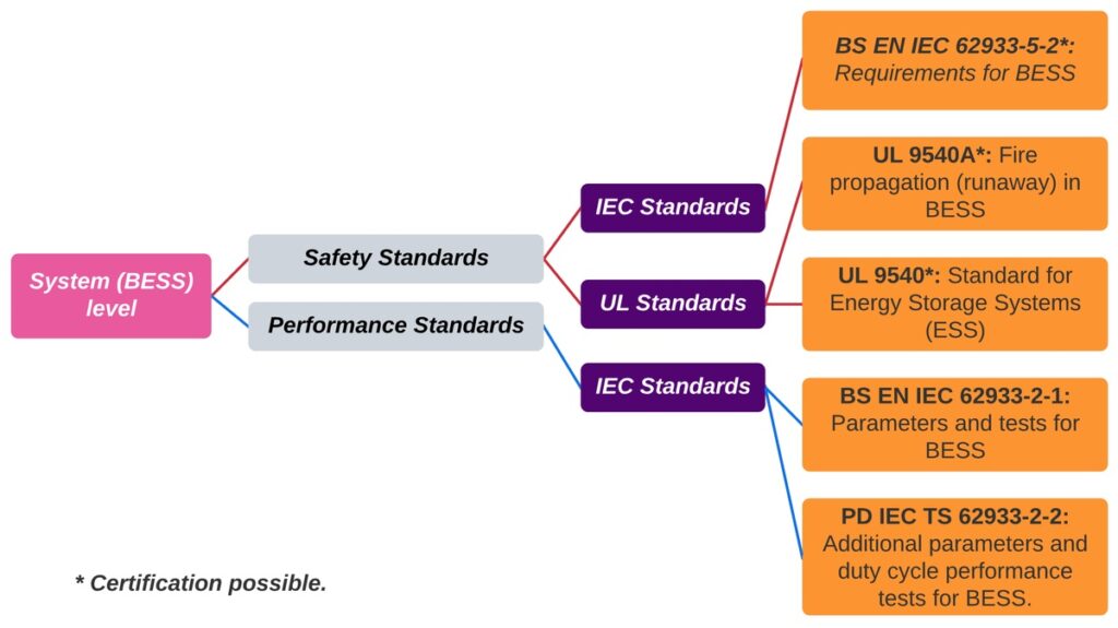
FATs and SATs are a staple of energy projects’ quality plans. They are initially justified by the fact that the client is buying (or installing) equipment, and therefore the system’s original safety and performance parameters must be verified. At the system level, these tests are specifically detailed in the IEC 62933 family of standards which takes into consideration the different types of energy storage systems (ESS) – mechanical, electrical, and electrochemical. Here, we cover the parameters and standards associated with electrochemical batteries.
Standard IEC TS 62933-3-1:2018 is a planning and performance assessment technical specification for ESS. It establishes what kinds of tests are needed to measure compliance with system specifications:
- From a performance standpoint, BS EN IEC 62933-2-1:2018 and the published document (PD) IEC TS 62933-2-2:2022 are the general specifications for parameter testing for an ESS, including a BESS.
- From a safety standpoint, FAT and SAT requirements specifically for electrochemical ESS, or BESS, are established in BS EN IEC 62933-5-2:2020, which specifies the test program to be carried out in the installations’ initial life stages. This standard’s scope is equivalent to the combined ANSI/CAN/UL 9540 standard along with the ANSI/CAN/UL 9540A test methodology. BESS manufacturers could certify their products under these three safety standards.
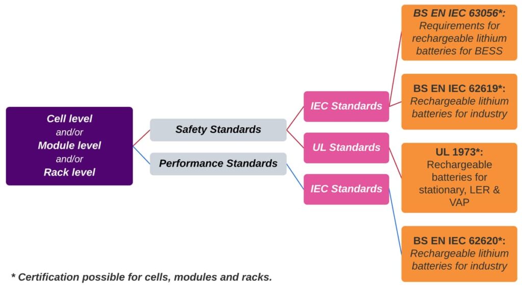
As batteries are the core element of a BESS, its components and electrochemical operating principle are inherently the most hazardous part of the system, and are thus where most of the safety measures should be focused. Standard BS EN IEC 63056:2020 is dedicated specifically to the assessment and testing of lithium batteries for use in a battery storage system. This standard falls under the umbrella of standard BS EN IEC 62619, which addresses the safety of rechargeable lithium cells and batteries for industrial use. Our opinion is that the tests mentioned in BS EN IEC 63056:2020 and BS EN IEC 62619:2022 should be performed for all batteries used in a BESS (or at least a sample as specified in these standards). Additionally, these two standards make a call to the performance standard IEC 62620:2014 regarding marking and capacity testing for the batteries. A battery OEM can certify its products (cells, modules and/or racks) under standards BS EN IEC 63056, 62619 and 62620. We found this combination the best option since most of the tests established look for potential triggers of fire, explosion or other dangerous situations, and these tests are required to be performed at the factory. We strongly recommend that test result reports be made available to the buyer and reviewed by an accredited independent engineer. We can help you with the latter.
It is worth mentioning that the ANSI/CAN/UL 1973 battery safety standard is equivalent to the three IEC battery standards mentioned before. Cells and batteries could also be certified using standard UL 1973. See figure 2 for the test standards available for BESS batteries.
In broad terms, the course of action for acceptance testing consists of:
- Type testing: done during manufacture or at the end of the production line of the major BESS components, to assess the standards conformity of representative production samples.
- FAT: done on complete and/or partially assembled subsystems, prior to their transportation to the site.
- SAT: done on the complete, installed system after commissioning.
Depending on the complexity of the BESS and other constraints such as manufacturing delays or component unavailability, some tests could be undertaken in either of FAT and SAT, before or after commissioning, and the results included in the installation’s operation manual as complete examination records.
Consequently, we always push for detailed FAT and SAT procedures for the system whilst assessing the batteries, in technical requirements (i.e. in the Employer Requirements or Minimum Functional Specification). We have established comprehensive and versatile FAT and SAT protocols considering the clients’ needs, and the availability and usual constraints of suppliers, along with always emphasizing safety without ignoring performance.
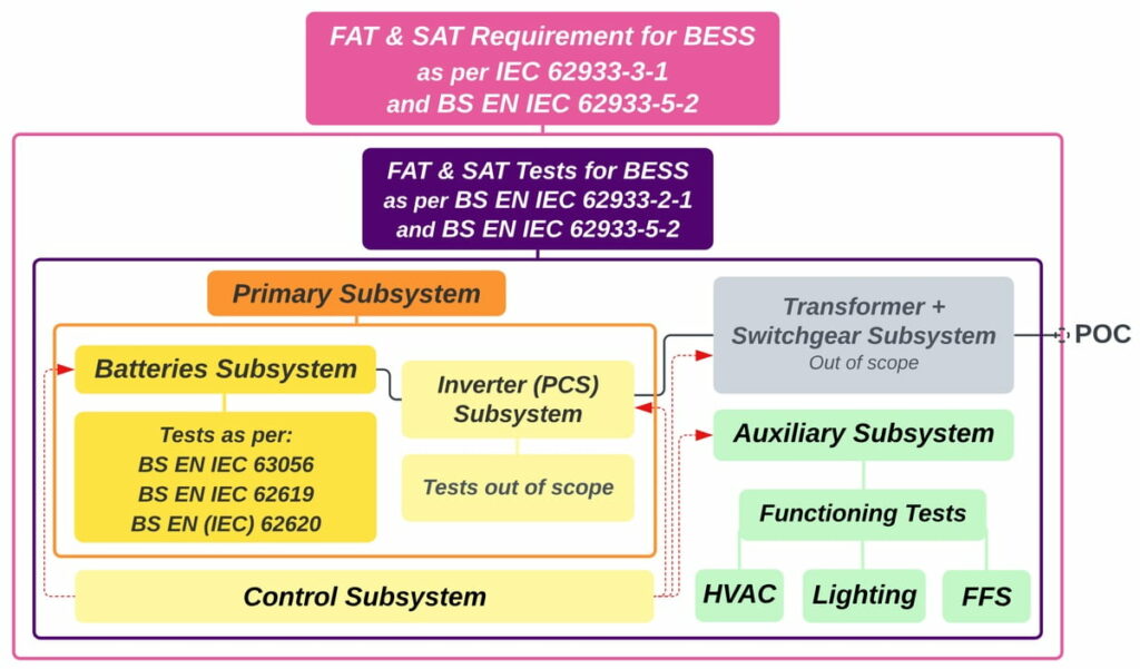
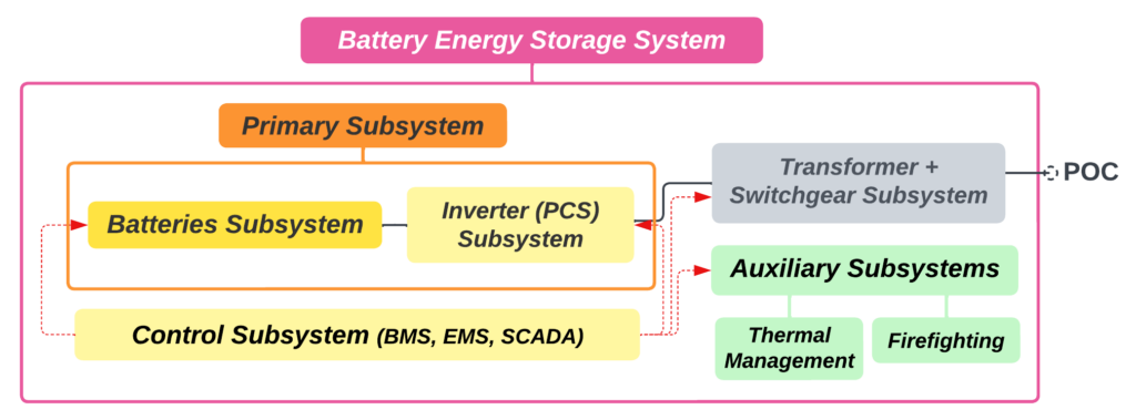
Our core methodology is pragmatically categorised into three levels, as shown in Figure 3:
- Pink Boundary: The establishment of the need for safety and performance FATs and SATs for BESS, and general guidelines as per the mentioned standards.
- Purple Boundary: Performance tests for a completely assembled BESS, usually conducted at the point of connection (POC) with the grid. For safety, the system must be evaluated as a whole, but every subsystem that composes it should individually be proven safe. Type tests, specific subsystems´ FAT and functioning tests should be performed for the major components of the system.
- Orange Boundary: Assessment of the BESS’s primary subsystem, which comprises the batteries and the power conversion system (PCS). If the PCS is not available, the batteries should be tested according to the applicable standards.
List of Standards
BS EN IEC 62619:2022. Secondary cells and batteries containing alkaline or other non-acid electrolytes – Safety requirements for secondary lithium cells and batteries for use in industrial applications.
BS EN 62620:2015. Secondary cells and batteries containing alkaline or other non-acid electrolytes – Secondary lithium cells and batteries for use in industrial applications.
(This standard is identical to IEC 62620:2014).
BS EN IEC 63056:2020. Secondary cells and batteries containing alkaline or other non-acid electrolytes - Safety requirements for secondary lithium cells and batteries for use in electrical energy storage systems
IEC TS 62933-3-1:2018. Electrical energy storage (EES) systems - Part 3-1: Planning and performance assessment of electrical energy storage systems - General specification.
BS EN IEC 62933-2-1:2018. Electrical energy storage (EES) systems - Part 2-1: Unit parameters and testing methods - General specification.
PD IEC TS 62933-2-2:2022. Electrical energy storage (EES) systems - Part 2-2: Unit parameters and testing methods - Application and performance testing.
BS EN IEC 62933-5-2:2020. Electrical energy storage (EES) systems - Part 5-2: Safety requirements for grid-integrated EES systems - Electrochemical-based systems.
ANSI/CAN/UL 1973:2022. Batteries For Use in Stationary And Motive Auxiliary Power Applications.
ANSI/CAN/UL 9540 Ed. 1-2016. Energy Storage Systems and Equipment.
ANSI/CAN/UL 9540A Ed. 4-2019. Test Method for Evaluating Thermal Runaway Fire Propagation in Battery Energy Storage Systems.
About the Authors
Tomas Gomez – Guest, Mechanical Engineer with more than 13 years of experience in oil & gas project construction. Eager about my newfound purpose: helping with the transition to clean energy and decarbonizing through quality engineering. https://www.linkedin.com/in/gomeztag/
Andres Blanco – Project Consultant | Managing Director at Blanboz, engineer with almost 15 years of experience in the renewable energy field, with the last seven to eight of these years fully dedicated to BESS through the full project life cycle. Electricity for all - Batteries lead the charge. Further information at www.blanboz.com, if you want to contact me please do so at a.blanco@blanboz.com, https://www.linkedin.com/in/andresblanco77
In our previous blog article, we discussed what tests should be applied to Battery Energy Storage Systems (BESS) during factory acceptance tests (FATs) and site acceptance tests (SATs). But how do we assess a BESS from a technology and configuration standpoint to ensure that it matches current sector parameters and features in terms of performance and safety?
This is where current standards come into play. As we mentioned before, standards organisations work tirelessly to keep up with advances in lithium-based battery and BESS technologies, so the use of these guidelines and/or specifications – created by globally recognised experts and authorities in the sector – is essential. This article maps out the relevant standards that apply to a BESS.
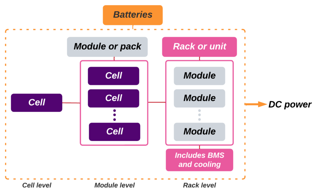
When we talk about standards, the key is understanding that a BESS is a whole comprised of the sum of its parts. Thus, by turning a BESS upside down and starting from its smallest part, we get the following:
- The cell Is the most basic part of the battery, which stores and generates a direct current (DC) from an electrochemical reaction between its components.
- If we connect a group of cells in parallel and in series and enclose them, we now have a module (or pack)1.
- Finally, if we stack several modules together, we now have a battery rack.
A cell, module, or rack capable of storing DC energy is the reservoir part of a battery storage plant, equivalent to the water in a hydropower plant. A power conversion system is required to turn this stored energy into power, like the turbine in a hydropower plant.
For BESS, the power conversion system (PCS) is an inverter (a power electronic device) that turns the batteries' DC power into AC power. Please note that there is a slight difference between the power conversion system and the power conditioning system across different standards, but we will leave that explanation for another discussion. In this article, we refer to PCS as the inverter.
Everything before the PCS is then “a battery.” Usually, the batteries’ energy capacity is described in terms of Watt-hours, because Energy = Power × Time. Downstream from the inverter (or PCS), it transforms into Watts, because Power = Energy/Time.
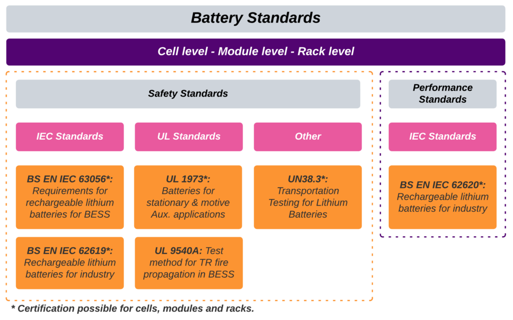
Batteries have specific minimum performance and safety requirements laid out by the standards we mentioned earlier. Standards at battery level usually discern between the cell, the module and the rack. For the standards on which a battery can be certified, this differentiation is stated. Usually, compliance with battery standards at cell, module and rack levels (as shown in Figure 1) is required.
At Blanboz, we consider that standards for BESS are generally divided into two distinct categories:
- American vs European (or International), e.g., IEC vs UL. We know it’s an oversimplification, but it helps us to understand better. We love them all.
- Safety standards vs performance standards.
Battery-level Safety Standards
Underwriters Laboratory (UL) is based in the U.S. and is completely authorised and approved by the Occupational Safety and Health Administration (OSHA) to write safety standards. Some of its standards are fundamental to BESS and are widely requested and recognised in the sector. Meanwhile, the standards-writing International Electrotechnical Commission (IEC) is based in Geneva, Switzerland, and is closely related to the International Standards Organization (ISO). IEC standards are international and based on contributions from basically every country worldwide, which means that their publications and guidelines are always vital.
At Blanboz, we consider UL 19732 the most comprehensive safety standard for batteries in a BESS, together with its IEC counterpart, IEC 62619.3 Both of these standards are widely adopted within the sector. We normally expect that the batteries on a BESS are certified to both UL and IEC standards at cell, module and rack levels.
It is worth noting that one of the first widely adopted lithium battery standards in the industry was UL 1642,4 but for BESS nowadays this standard is included and expanded in UL 1973. It is still quite common to find batteries certified to this standard in the industry as part of UL 1973 certification; however, UL 1642 by itself is a basic standard and lacks the completeness of UL 1973.
Additionally, for BESS the IEC 62619 standard is accompanied by the IEC 630565 standard. This is a relatively short standard of only 24 pages, under the umbrella of IEC 62619, and expands on the test requirements necessary for batteries used in a BESS. At Blanboz, we encourage users to follow this standard as well as IEC 62619. However, we understand that it is not currently widely adopted within the industry.
One of the main risks of lithium batteries is that if the temperature of the cells is not adequately controlled, it may start increasing uncontrollably in a chain reaction known as thermal runaway (TR). TR always starts at a cell level, but resources for its management and containment should occur at all levels of a BESS. This is where the UL 9540A6 test methodology comes in. Please note that UL 9540A is commonly but mistakenly believed to be a standard; it is only a test methodology. It originates from the UL 95407 standard, which is a safety standard for BESS (by which we mean the whole system, not just batteries!). The purpose of UL 9540A is to establish a test methodology to look for possible stimuli for TR at the cell level and to assess prevention and containment of the fire, or in other words evaluate fire propagation, at the module, rack and system levels. The methodology thus assesses the hazard management strategies of the system to mitigate the causes and consequences of TR. We expect various tests based on UL 9540A to be performed at several levels of a BESS.
Another common safety requirement for batteries is the transportation standard elaborated by the United Nations. It is contained in their Manual of Tests and Criteria, part III: Classification procedures, test methods and criteria relating to various hazard classes, Section 38.3: Lithium metal and lithium-ion batteries. It is commonly known simply as UN38.3.8 Batteries can be tested and certified to this standard from the cell up to the module level, to guarantee their safety during transportation.
Battery-level Performance Standards
Moving on from safety, when it comes to standards to assess the performance of lithium-based batteries for BESS usage we at Blanboz use IEC 626209 as our main reference. Check our previous blog article for a glimpse of our approach to battery performance testing or contact us for support!
See Figure 2 for an overview of the main standards for batteries for lithium-based BESS.
Battery Energy Storage Systems (BESS): System level
With the standards we identified and explained above, we can comprehensively assess the batteries of a BESS. However, when we get to the system or installation level, new subjects raise their heads. As shown in Figure 3, when we join the batteries with a PCS and start generating AC power, we have a BESS.10 Using IEC standards nomenclature, the combination of the batteries with the PCS is referred to as the primary subsystem.
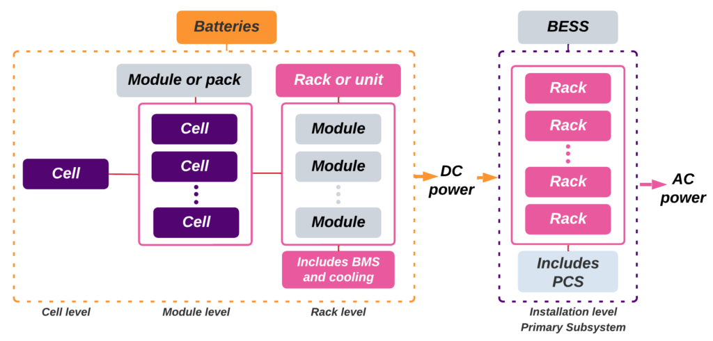
Figure 3 – Battery configuration shift into a BESS
Besides the above established primary subsystem, a BESS also has:
- A control subsystem comprised of the battery management system (BMS), the system’s energy management system (EMS) and remote control and communication capabilities (commonly known as SCADA, although we also like to emphasise the inclusion of battery controllers or power plant controllers).
- Auxiliary subsystems, of which the most important are:
- The thermal management of the components, which normally includes an HVAC system and – for the most recent BESS designs – a chiller for liquid cooling.
- System firefighting capabilities (fire prevention and suppression, and explosion prevention)
- Other auxiliary subsystems (e.g., lighting)
Sometimes the transformer and switchgear subsystem, which is the connection subsystem, is not considered. Both iterations are correct and either can be considered a BESS. See Figure 4 for the main components of a BESS.
With that in mind, each of these subsystems has standards that establish their desired characteristics; again, these standards are separated into safety and performance requirements. These specific standards are not covered in this article; however, the essential ones are referenced in the standards we will mention below.
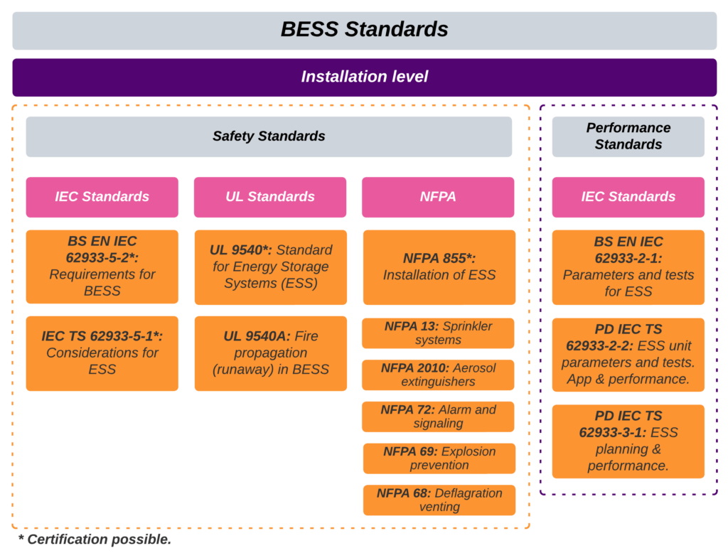
BESS Installation-level Safety Standards
At Blanboz, we consider the most comprehensive safety standards for BESS to be UL 9540, including its offspring test method UL 9540A, and its IEC counterpart IEC 62933-5-2,11 which acts in concert with IEC 62933-5-112. Notice from their titles that these standards are for any complete energy storage system (ESS), not only lithium-based ESS. They additionally consider the PCS, the communication system, the system enclosure, and the fire strategy (detection, suppression, explosion protection, and propagation) among other characteristics of complete installations. These standards compile all the minimum safety requirements for a BESS and make specific references to other required standards.
One thing we notice is that because UL 9540A focuses on the propagation of fire due to cell-level thermal runaway, this standard test method is always associated with batteries. In fact, it is an ESS standard that covers all the levels up to the installation level. Furthermore, this test method aims to assess the temperature, released gases and containment measures at everything from the battery level to the installation level. The standard evaluates the effectiveness of the sprinkler system and the fire protection plan for the entire BESS. Currently, assessment based on this standard is the industry's default setting, although the standard is not technically mandatory.
Additionally, the IEC 62933-5-2 and 62933-5-1 standards act as comprehensive standards (or guidelines), but due to the interlaced relationship between the NFPA and UL standards the IEC standards are not commonly encountered or widely adopted in the industry.
Having just mentioned NFPA standards, we should explain what they are. The National Fire Protection Association is a U.S.-based standards organisation focused on fire prevention and mitigation. When it comes to BESS, its standards are completely recognised and adopted by the industry. A completely fireproof BESS must have fire prevention, suppression, and explosion prevention capabilities. These properties are detailed in the following NFPA standards:
NFPA 13: 2019 Standard for the Installation of Sprinkler Systems
NFPA 2010: 2019 Standard for Fixed Aerosol Fire-Extinguishing Systems
NFPA 72: 2018 National Fire Alarm and Signalling Code
NFPA 69: 2018 Standards on Explosion Prevention Systems
NFPA 68: 2018 Standard on Explosion Protection by Deflagration Venting
The specific firefighting requirements for BESS are summarised in what we consider the most comprehensive guideline for fire management best practices, the NFPA 85513 standard, which is a complete and detailed compilation of fire safety requirements for BESS. It is closely related to BESS UL standards, as their requirements intertwine. Because fire is always a crucial concern with BESS, we always recommend full compliance with NFPA 855 and related standards.
The Relationship between NFPA 855 and UL 9540
NFPA 855 standards are the minimum requirements for hazard mitigation regarding fire whereas UL 9540 is an overall compatibility and safety standard. Both of these standards are for all types of ESS and include electrochemical-based energy storage systems (BESS).
Chapter 4 of the 2023 version of NFPA 855 declares that storage systems must be formally evaluated (listed) in accordance with UL 9540. This requirement is also present in the 2020 version of the NFPA 855 standard.
Additionally, Annex A of the 2023 version of NFPA 855 basically states that an equivalent or superior system or method regarding safety may be used to assess a storage system. We will provide further analysis and a comparison between UL 9540 and its IEC counterparts regarding equivalency or superiority in terms of safety in a future blog article. Currently, NFPA 855 does not explicitly mention any other organisation’s equivalent safety standard to UL 9540.
Finally, NFPA 855: 2023 mentions that existing lithium-ion ESS that are not UL 9540 listed require their hazard mitigation analysis (HMA) to be reviewed by project-specific competent authorities. Conducting an HMA is always considered an industry best practice. If you need assistance creating a hazard mitigation analysis or have any concern related to the safety compliance of your BESS do not hesitate to contact us.
BESS Installation-level Performance Standards
For performance, the tables turn and IEC standards become the go-to reference for assessing the functioning and performance capabilities of your installation. The main performance assessment standard for a BESS is IEC 62933-2-114. It reigns supreme because all measurements of active power, reactive power, energy capacity and round-trip efficiency, among other performance measurements, are well defined in it.
This standard is accompanied by the technical specifications IEC TS 62933-2-215 and IEC TS 62933-3-116, which further detail and specify performance tests for a BESS in different scenarios.
Finally, we refuse to end this article without mentioning that, even though there is no current standard that deals with the performance of a BESS’s thermal management system either with HVAC and/or liquid-cooling that we are aware of, this is one of the main topics, if not the main topic to address when assessing BESS performance. We agree with the famous tech YouTuber Marques Brownlee: “What ruins your battery is heat.”17 Consequently, we consider that a thorough evaluation of the BESS cooling system at the cell level using computational fluid dynamics (CFD) and/or real-world testing should be performed to guarantee that cell temperature does not increase above the recommended limits. We expect that in the future, all BESS manufacturing companies should show their detailed heat management data for clients to review.
Figure 5 shows an overview of Installation-level standards for BESS. If you need further assistance with a technology review, technical due diligence, or the creation of a technical employer’s requirement, at Blanboz we can help you!
Inverter or PCS Standards
Finally, when we specifically need to assess the safety characteristics of a PCS, we can do so easily because it is a mature and well-standardised piece of equipment (thanks to the solar photovoltaic industry, among others). Accordingly, we look for evaluations and/or certifications on UL 174118, including its supplement B (UL 1741 SB), and/or IEC 62109-119 and IEC 62109-220. These are safety standards and cover the device’s construction requirements and the applicable tests to be performed on it. They are therefore widely used in the industry. Because the PCS serves as the interface between the batteries and the grid, converting DC power to AC power and vice versa, and/or setting electrical parameters such as voltage and frequency, the assessment of its performance and capabilities is included in the testing of the BESS as a complete system and is detailed in the IEC 62933 family of standards.
About the Authors:
Tomas Gomez – Guest, Mechanical Engineer with more than 13 years of experience in oil & gas project construction. Eager about my newfound purpose: helping with the transition to clean energy and decarbonising through quality engineering. https://www.linkedin.com/in/gomeztag/
Andres Blanco – Project Consultant | Managing Director at Blanboz, an engineer with almost 15 years of experience in the renewable energy field, with the last seven to eight of these years fully dedicated to BESS through the full project life cycle. Electricity for all - Batteries lead the charge. Further information at www.blanboz.com , if you want to contact me, please do so at a.blanco@blanboz.com , www.linkedin.com/in/andresblanco77
- The term module is very common in the sector; however, this configuration is also known as a pack by some standards and other publications. ↩︎
- ANSI/CAN/UL 1973:2022. Batteries For Use in Stationary And Motive Auxiliary Power Applications. ↩︎
- BS EN IEC 62619:2022. Secondary cells and batteries containing alkaline or other non-acid electrolytes – Safety requirements for secondary lithium cells and batteries for use in industrial applications. ↩︎
- UL 1642 Ed. 6-2020. Lithium Batteries. ↩︎
- BS EN IEC 63056:2020. Secondary cells and batteries containing alkaline or other non-acid electrolytes - Safety requirements for secondary lithium cells and batteries for use in electrical energy storage systems. ↩︎
- ANSI/CAN/UL 9540A Ed. 4-2019. Test Method for Evaluating Thermal Runaway Fire Propagation in Battery Energy Storage Systems. ↩︎
- ANSI/CAN/UL 9540 Ed. 3-2023. Energy Storage Systems and Equipment. ↩︎
- UN38.3: Transportation Testing for Lithium Batteries ↩︎
- IEC 62620:2014/AMD1:2023. Secondary cells and batteries containing alkaline or other non-acid electrolytes – Secondary lithium cells and batteries for use in industrial applications. ↩︎
- DC ESS are a possibility, and it is within the scope of UL 9540 to assess them, however, we consider that AC ESS are the most common type of BESS and the focus of this article. ↩︎
- BS EN IEC 62933-5-2:2020. Electrical energy storage (EES) systems - Part 5-2: Safety requirements for grid-integrated EES systems - Electrochemical-based systems. ↩︎
- IEC TS 62933-5-1:2017. Electrical energy storage (EES) systems - Part 5-1: Safety considerations for grid-integrated EES systems - General specification ↩︎
- NFPA 855: 2023. Standard for the Installation of Stationary Energy Storage Systems ↩︎
- BS EN IEC 62933-2-1:2017. Electrical energy storage (EES) systems - Part 2-1: Unit parameters and testing methods - General specification. ↩︎
- BS PD IEC TS 62933-2-2:2022. Electrical energy storage (EES) systems - Part 2-2: Unit parameters and testing methods - Application and performance testing. ↩︎
- IEC TS 62933-3-1:2018. Electrical energy storage (EES) systems - Part 3-1: Planning and performance assessment of electrical energy storage systems - General specification. ↩︎
- YouTube video. Does Fast Charging ACTUALLY Ruin Your Battery? https://youtu.be/UpqaQR4ikig?si=-DGnPIGOAj05I1pS ↩︎
- UL 1741 Ed. 3-2021. Inverters, Converters, Controllers and Interconnection System Equipment for Use with Distributed Energy Resources ↩︎
- IEC 62109-1:2010. Safety of power converters for use in photovoltaic power systems - Part 1: General requirements ↩︎
- IEC 62109-2:2011. Safety of power converters for use in photovoltaic power systems - Part 2: Particular requirements for inverters ↩︎
Those whom I have worked with in the past know that I am an advocate for explosion safety and prevention in BESS during the design, construction and in operational stages. I recently got asked if an explosion was less likely to happen than a fire. My gut feeling is that it might be. Still, I reckon that the impact of a blast could be more harmful than that of fire due to the unknowns and the high degree of uncertainties in thermal runaway gas mixture, explosion behaviour and shock wave impact, and more importantly the surprise and silent effect. This is one of the main issues that I have with the “let it burn” approach.
I recently read an excellent paper “An analysis of li-ion induced potential incidents in battery electrical energy storage system by use of computational fluid dynamics modeling and simulations: The Beijing April 2021 case study” by authors in the reference below*.
My interpretation is that sadly, two lives were lost in 2021 in an explosion involving Li-ion BESS (LFP type) in Beijing, China. Apart from the sad loss of two lives (firefighters), what left my mouth wide open reading the paper was that the fire originated in one building and the explosion happened in a separate building around 20 m apart, almost 2.5 hours after the fire initiation. I definitely recommend giving it a read, it is a worthwhile investment (unfortunately it is not an open source).
Key intakes that I learned from reading this paper:
- The craziest point, that I hadn't thought about, but it's entirely logical, is that explosive gas can travel through underground cable trenches/ducting from your BESS containers to other rooms. This is particularly important for those housing equipment in buildings.
- “...batteries in high SOC release more types of thermal runaway gas, with higher fire and explosion risks…” I never thought about this from this angle. This emphasises the importance of having UL9540A tests carried out at the system level and not only at the cell or module levels.
- 50-100 kPa and over 100 kPa (14.5 psi or 1 bar) blast pressures are enough to either harm you for life or take your life completely. From reading the paper, I interpreted that the pressure estimated at the location of the lost firefighters was around 70 kPa; when near the ignition source, it was estimated at 37 kPa.
- Shock waves can lead to greater overpressure risk and damage than at the source of initiation. I believe that overpressure release panels sometimes do not work due to the quick pressure overbuilt that overwhelms the pressure rating of these protection devices. Relaying only to this type of prevention is only a sweetener, in my opinion. Therefore, there should be more thoughts about it and my issues with the NFPA 68. Open for debate.
- There is a stigma around LFP being fire-safer than NMC battery chemistry. This is not necessarily true. Both chemistries are highly sensitive to mechanical and thermal abuses. Or in other words, how we operate them. Human-lead errors.
- The importance of computational fluid dynamics from BESS OEMs first, following the entire project quantitative risk assessments for fires and explosions (including different overpressure curve scenarios). These should be a planning requirement alongside full fire and explosion prevention and suppression safety systems in design, construction and operation. In addition to emergency response plans before and after an explosion/fire event. Independent technical experts (such as Blanboz) and fire brigades must previously authorise these.
Could this explosion event in Beijing have been prevented? Probably yes. How? In-Country regulations and requirements specifically applied to the BESS in the design, construction and operational stages. In addition to the critical role that standards and safety certifications play in the BESS industry. Are the NFPA 68 and 69 the best? Well in my personal opinion, they aren't. But these standards are probably the best we currently have in the industry which can also open debate for further improvement. Nevertheless, the role that emergency response plans play and the responsibilities that the BESS OEM shares in the HSE of a project. Remember that we all have a role in the success and safety of this industry.
*Paper’s reference:
Xingyu Shen, Qianran Hu, Qi Zhang, Dan Wang, Shuai Yuan, Juncheng Jiang, Xinming Qian, Mengqi Yuan. An analysis of li-ion induced potential incidents in battery electrical energy storage system by use of computational fluid dynamics modeling and simulations: The Beijing April 2021 case study.Engineering Failure Analysis,Volume 151,2023,107384,ISSN 1350-630.
https://doi.org/10.1016/j.engfailanal.2023.107384

About the author:
Andres Blanco – Project Consultant | Managing Director at Blanboz, I’m an engineer with almost 15 years of experience in the renewable energy field, with the last seven to eight of these years fully dedicated to BESS through the full project life cycle. I am also passionate about explosion and fire prevention and suppression’s implementation in BESS. Electricity for all - Batteries lead the charge. Further information at www.blanboz.com , if you want to contact me, please do so at a.blanco@blanboz.com , www.linkedin.com/in/andresblanco77